Question for ya bud
Why r u maintaining a negative instead of positive air pressure status in ur grow zone?
Welcome to the grow room designs and equipment section. Every grower faces different obstacles when setting up a cannabis grow room. Use this section to discuss the different types of grow rooms you use or would like information about to grow cannabis. To become part of our online cannabis growing community click here to register.
DIY Data Logger - Dabbling with Arduino
-
Mafooo

- Registered User
- Posts: 1991
- Joined: Sat Feb 22, 2020 4:32 am
- Location: MafoooFarms on Instagram
- Has thanked: 1020 times
- Been thanked: 1049 times
- Status: Offline
-
weedabix

- Registered User
- Posts: 475
- Joined: Mon Dec 02, 2019 9:12 am
- Has thanked: 148 times
- Been thanked: 123 times
- Contact:
- Status: Offline
Re: DIY Data Logger - Dabbling with Arduino
I want air to be sucked into the grow space, so smell can't exit it. I know my fan is working if the pressure in the tent is below the pressure outside. I think my fan is a bit overkill - I'd get away with a smaller difference, as long as the pressure inside is lower, all air from the growtent will have to pass through the carbon filter. Whether it's plotted as a positive value (300 Pa rather than -300Pa) is arbitrary, as long as I know what's happening!Mafoo.Martin wrote: ↑Sat Apr 04, 2020 1:36 pmWhy r u maintaining a negative instead of positive air pressure status in ur grow zone?
- this sounds like a cool project but feels like it's quite a step up in terms of knowhow and a bit of a step in terms of price of components.grumpygrower wrote: ↑Sat Apr 04, 2020 12:18 pmMy idea was to make some of the sensors wireless using zigbee mesh.
I am now even more hooked and I'm keen to add a keypad to enter values such as EC, pH, and runoff EC manually so they are being recorded. Maybe I should take a break before I spend the rest of the weekend on it!
-
G3W2HIN

- Registered User
- Posts: 1146
- Joined: Fri Nov 01, 2019 8:20 pm
- Location: USA
- Has thanked: 183 times
- Been thanked: 359 times
- Contact:
- Status: Offline
Re: DIY Data Logger - Dabbling with Arduino
Wow man the project is awesome, I need sensors to get my pi zero running in my tent ,for now the pi is a sad attempt at a time lapse camera, works better as a surveillance camera really on this motioneyeos system. Have to pick your brain one of these days . Good on ya man
From the middle of T.B.2, B.F.E. sector OU812 in cluster F. using Tapatalk.. inner peace
From the middle of T.B.2, B.F.E. sector OU812 in cluster F. using Tapatalk.. inner peace
INNER PEACE
-
Minty

- Registered User
- Posts: 3893
- Joined: Sat Apr 18, 2020 7:21 pm
- Has thanked: 3802 times
- Been thanked: 1494 times
- Status: Offline
Re: DIY Data Logger - Dabbling with Arduino
Looking good - I also use an Arduino running Figmata and communicate with it using Johnny-five which allows the software to be written in JavaScript.


-
Neilw420
- Registered User
- Posts: 116
- Joined: Sat Apr 18, 2020 6:14 pm
- Has thanked: 22 times
- Been thanked: 34 times
- Status: Offline
Re: DIY Data Logger - Dabbling with Arduino
Just buy a minder from pl growsystems does all the logging you need
-
weedabix
- Registered User
- Posts: 475
- Joined: Mon Dec 02, 2019 9:12 am
- Has thanked: 148 times
- Been thanked: 123 times
- Contact:
- Status: Offline
Re: DIY Data Logger - Dabbling with Arduino
It does less than my system does but costs £100 - about 10 times what I paid for the components.
-
Minty
- Registered User
- Posts: 3893
- Joined: Sat Apr 18, 2020 7:21 pm
- Has thanked: 3802 times
- Been thanked: 1494 times
- Status: Offline
Re: DIY Data Logger - Dabbling with Arduino
Been there and still doing it. I tried the following sensors and the only one I got a decent stable reading from was the BME280:-weedabix wrote: ↑Fri Jan 24, 2020 9:19 amI have the feeling the humidity is being reported very low. It is consistently at least 5% under the hygrometer I got off amazon - which is lying on the ground, whereas the sensor is fixed to a skewer in the pot. Maybe it's a problem of the long cable, maybe a calibration issue, maybe it is real and there is a gradient within the tent or the other meter is not working properly.
The biggest problem is knowing which one is reporting correctly so you can fix the others.
I even have a PR open with Johnny-Five to address one of the issues I hit.
Fecking Awesome Idea mate - why didn't I think of that!,
BME280 has a barometer and it totally never occurred to me to use it for checking the fans are actually working!
The Arduino should be able to tell the difference between all combinations of the Intake & Extract being on/off and this feedback is valuable information for an automated solution. You Sir, are a Genius ;o)
Not so sure about detecting the oscillating air movement fans but this is no big deal and the BME does also have an altitude readings, but unless I mount in a float sensor I don't think I will be using that one (I will not be mounting in anywhere near the water) .
Totally feel your pain brother. I would say using I2C for most of the complicated sensors/drivers/etc resolves the PIN limitation but I still need more 'God Damn PINs' for that 'other' idea I just had...
Trust me I hit this PIN limitation big time and my current condensed PIN assignment is:-
Code: Select all
/* RF433 Transmitter Support */
config.RCT_IN_PIN = 6;
config.RCT_OUT_PIN = 7;

* HWR = Hardware Relays 240v */
config.HWR_RELAY_ONE_PIN = 4; // WATER PUMP
config.HWR_RELAY_TWO_PIN = 5; // WATER HEATER

/* WLS = Water Level Switches */
config.WLS_RES_LOW_PIN = 9;
config.WLS_RES_HIGH_PIN = 10;
config.WLS_TANK_LOW_PIN = 11;
config.WLS_TANK_HIGH_PIN = 12;Code: Select all
config.I2C_GROVE_TEMP_HUMIDITY_ADDR = (0x40);
config.I2C_ADAFRUIT_MOTORBOARD_TWO_ADDR = (0x60);
config.I2C_ADAFRUIT_MOTORBOARD_ONE_ADDR = (0x61);
config.I2C_ATLAS_PH_SENSOR_ADDR = (0x63);
config.I2C_ATLAS_EC_SENSOR_ADDR = (0x64);
config.I2C_ATLAS_TEMP_SENSOR_ADDR = (0x66);
config.I2C_ADAFRUIT_MOTORBOARD_ALL_CALL_ADDR = (0x70);
config.I2C_BME280_SENSOR_ADDR = (0x76);I managed to 'offload' a load of OUTPUT pins by using remote devices controlled via the RF433mhz signals so no internet connection required etc. but even these soon accumulated:-
Code: Select all
/* Air Intake Fan */
const RF_CODE_INTAKE_LOW = "7446194";
const RF_CODE_INTAKE_HIGH = "7446193";
const RF_CODE_INTAKE_OFF = "7446196";

/* Minty HumiBox - Humidifier */
const RF_CODE_HUMID_LOW = "12562584";
const RF_CODE_HUMID_HIGH = "12562578";
const RF_CODE_HUMID_OFF_LOW = "12562580";
const RF_CODE_HUMID_OFF_HIGH = "12562577";

/**
 * Geekcreit® 12V 4CH Channel 433Mhz
 * Following RF codes will toggle all relay channels at once
 * e.g. to open Relays 2&4 and close Realys 1&3 we send 2775141
 * RELAY_CHANNEL_1234 Where 0=CLOSED 1=OPEN
 */

const RF_CODE_12V = {
  RF_0000: "2775136",
  RF_0001: "2775137",
  RF_0010: "2775138",
  RF_0011: "2775139",
  RF_0100: "2775140",
  RF_0101: "2775141",
  RF_0110: "2775142",
  RF_0111: "2775143",
  RF_1000: "2775144",
  RF_1001: "2775145",
  RF_1010: "2775146",
  RF_1011: "2775147",
  RF_1100: "2775148",
  RF_1101: "2775149",
  RF_1110: "2775150",
  RF_1111: "2775151",
}

config.MINTY_FDD = {
  RES: RF_CODE_12V.RF_0001,
  POTS: RF_CODE_12V.RF_0010,
  DRAIN: RF_CODE_12V.RF_0011,
  FILL: RF_CODE_12V.RF_0100,
  DRIP: RF_CODE_12V.RF_1000,
  OFF: RF_CODE_12V.RF_0000,
}

/* Etekcity Wireless Remote Control Sockets */
const RF_CODE_S1_ON = "5264691"; // Dehumidifier
const RF_CODE_S1_OFF = "5264700";
const RF_CODE_S2_ON = "5264835"; // Air Heater
const RF_CODE_S2_OFF = "5264844";
const RF_CODE_S3_ON = "5265155"; // Air Fan Large
const RF_CODE_S3_OFF = "5265164";
const RF_CODE_S4_ON = "5266691"; // Air Extract
const RF_CODE_S4_OFF = "5266700";
const RF_CODE_S5_ON = "5272835"; // Light
const RF_CODE_S5_OFF = "5272844";

/* Energenie Trailing Gang with Four Radio Controlled Surge Protected Sockets */
const RF_CODE_Q1_ON = "8950879"; // SPARE
const RF_CODE_Q1_OFF = "8950878";
const RF_CODE_Q2_ON = "8950871"; // CAMERA
const RF_CODE_Q2_OFF = "8950870";
const RF_CODE_Q3_ON = "8950875"; // Air Pump
const RF_CODE_Q3_OFF = "8950874";
const RF_CODE_Q4_ON = "8950867"; // Air Fan Small
const RF_CODE_Q4_OFF = "8950866";
const RF_CODE_QALL_ON = "8950877"; // Extention Block Over-ride
const RF_CODE_QALL_OFF = "8950876";My setup is using the Pi for basically the Wifi and to run the Web Server, Database and backend. You could do this on a PC but you really need the WIFI point close to the tent which is why I plan to it on the Pi Zero W.
Congrats dude and well done on what you have achieved - I know as I have been doing myself and to be honest it is great fun tinkering for the greater purpose.
If you need any help with any of your stuff give me a shout mate and I would be willing to contribute or just chuck some ideas around.
-
Minty
- Registered User
- Posts: 3893
- Joined: Sat Apr 18, 2020 7:21 pm
- Has thanked: 3802 times
- Been thanked: 1494 times
- Status: Offline
Re: DIY Data Logger - Dabbling with Arduino
Is your software open source? Wouldn't mind taking a look and seeing what else I can incorporate into my own
-
weedabix
- Registered User
- Posts: 475
- Joined: Mon Dec 02, 2019 9:12 am
- Has thanked: 148 times
- Been thanked: 123 times
- Contact:
- Status: Offline
Re: DIY Data Logger - Dabbling with Arduino
Hi Minty,
thanks for your kind words! That is a very detailed answer and to be honest I have had some weed and some beers so I'll reply more detailed tomorrow. It is actually still working and I quite like it - it has helped me a couple of times, mostly to see whether the light is working because it has a dodgy power connection (it's a pile of shit - a bright blurple pile if I am lucky). I am using a BME280 and a BMP280 (that was sent to me as a BME280) running on an ESP8266 each. I'll share some more data and read your reply carefully tomorrow!
thanks for your kind words! That is a very detailed answer and to be honest I have had some weed and some beers so I'll reply more detailed tomorrow. It is actually still working and I quite like it - it has helped me a couple of times, mostly to see whether the light is working because it has a dodgy power connection (it's a pile of shit - a bright blurple pile if I am lucky). I am using a BME280 and a BMP280 (that was sent to me as a BME280) running on an ESP8266 each. I'll share some more data and read your reply carefully tomorrow!
-
weedabix
- Registered User
- Posts: 475
- Joined: Mon Dec 02, 2019 9:12 am
- Has thanked: 148 times
- Been thanked: 123 times
- Contact:
- Status: Offline
Re: DIY Data Logger - Dabbling with Arduino
Hi Minty,
loving your setup - you're way ahead and I love the multitude of monitoring and controlling options you have! So my setup is really quick and dirty in comparison: one BME280 inside the tent and one BMP280 outside (so I can measure the pressure difference to see whether the fan is working) I upload everything to thingspeak. There I have a few options to use the data. I wanted to use both BME280's on one Nodemcu but failed - I can't find a good library that works for me, or it's just the fact that one of them is a BMP280. The code is a mix of copied and pasted things I found online so don't quote me when using it!
The VPD and the pressure difference is calculated online on thingspeak - also modifying their templates!
The results are quite good - I was keeping a closer eye on the VPD initially but now I am more concerned with the light - and there have been oocasions when I was too lazy to check whether I turned the light back on or whether it turned itself off again and I could just quickly check on my phone - so that £0.30 sensor is well worth the price!
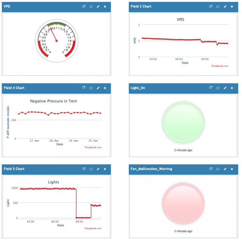
on the image you can see the button that goes green when the light sensor is above a certain voltage, the pressure button goes red if the pressure difference is below I believe 200 Pa and the VPD is based on an assumed leaf temperature of 2C below the ambient temperature. After I started using a dedicated power source and not the usb port of the power bar (which always drops voltage when the light goes on!) it now runs very reliably - 20 days and counting without a signal loss!
I really like your project! Do you have it written up somewhere? I'd be interested to know what pH and EC sensor you're using, are they reliable?
I am really only learning while doing this and am a total newbie and it's cool to see how far you're taking this!
cheers,
Weedabix
loving your setup - you're way ahead and I love the multitude of monitoring and controlling options you have! So my setup is really quick and dirty in comparison: one BME280 inside the tent and one BMP280 outside (so I can measure the pressure difference to see whether the fan is working) I upload everything to thingspeak. There I have a few options to use the data. I wanted to use both BME280's on one Nodemcu but failed - I can't find a good library that works for me, or it's just the fact that one of them is a BMP280. The code is a mix of copied and pasted things I found online so don't quote me when using it!
Code: Select all
 //BME280 Thing Speak project
//PKI-IEEE
//Takumi Ito
//3/3/2020

#include "ThingSpeak.h" //install library for thing speak
#include <ESP8266WiFi.h>
#include <BME280I2C.h>
#include <Wire.h>

char ssid[] = "SSID";        // your network SSID (name)
char pass[] = "PW";    // your network password
int keyIndex = 0;            // your network key Index number (needed only for WEP)
WiFiClient  client;
BME280I2C bme;

unsigned long myChannelNumber = the channel number here;
const char * myWriteAPIKey = "my API key";

// Initialize our values
String myStatus = "";

float temp(NAN), hum(NAN), pres(NAN);


void setup() {
  Serial.begin(115200);  //Initialize serial

  //WiFi.mode(WIFI_STA);
  ThingSpeak.begin(client);  // Initialize ThingSpeak

  Wire.begin();

  while(!bme.begin())
  {
    Serial.println("Could not find BME280 sensor!");
    delay(1000);
  }

  // bme.chipID(); // Deprecated. See chipModel().
  switch(bme.chipModel())
  {
     case BME280::ChipModel_BME280:
       Serial.println("Found BME280 sensor! Success.");
       break;
     case BME280::ChipModel_BMP280:
       Serial.println("Found BMP280 sensor! No Humidity available.");
       break;
     default:
       Serial.println("Found UNKNOWN sensor! Error!");
  }
}

void loop() {

  // Connect or reconnect to WiFi
  if(WiFi.status() != WL_CONNECTED){
    Serial.print("Attempting to connect to SSID: ");
    Serial.println(ssid);
    while(WiFi.status() != WL_CONNECTED){
      WiFi.begin(ssid, pass);  // Connect to WPA/WPA2 network. Change this line if using open or WEP network
      Serial.print(".");
      delay(5000);
    }
    Serial.println("\nConnected.");
  }

  BME280::TempUnit tempUnit(BME280::TempUnit_Celsius);
  BME280::PresUnit presUnit(BME280::PresUnit_Pa);

  bme.read(pres, temp, hum, tempUnit, presUnit);
int sensorValue = analogRead(A0);   // read the input on analog pin 0

  float voltage = sensorValue * (1000 / 1023.0);   // Convert the analog reading (which goes from 0 - 1023) to a voltage (0 - 5V)


  Serial.print("Temp: ");
  Serial.print(temp);
  Serial.print("°"+ String(tempUnit == BME280::TempUnit_Celsius ? 'C' :'F'));
  Serial.print("\t\tHumidity: ");
  Serial.print(hum);
  Serial.print("% RH");
  Serial.print("\t\tPressure: ");
  Serial.print(pres);
  Serial.println(" Pa");
Serial.print(voltage);   // print out the value you read
Serial.println("  Light");

  // set the fields with the values
  ThingSpeak.setField(1, temp);
  ThingSpeak.setField(2, hum);
  ThingSpeak.setField(3, pres);
  ThingSpeak.setField(4, voltage);


  // set the status
  ThingSpeak.setStatus(myStatus);

  // write to the ThingSpeak channel
  int x = ThingSpeak.writeFields(myChannelNumber, myWriteAPIKey);
  if(x == 200){
    Serial.println("Channel update successful.");
  }
  else{
    Serial.println("Problem updating channel. HTTP error code " + String(x));
  }

  delay(60000); // Wait 20 seconds to update the channel again
}
The results are quite good - I was keeping a closer eye on the VPD initially but now I am more concerned with the light - and there have been oocasions when I was too lazy to check whether I turned the light back on or whether it turned itself off again and I could just quickly check on my phone - so that £0.30 sensor is well worth the price!
on the image you can see the button that goes green when the light sensor is above a certain voltage, the pressure button goes red if the pressure difference is below I believe 200 Pa and the VPD is based on an assumed leaf temperature of 2C below the ambient temperature. After I started using a dedicated power source and not the usb port of the power bar (which always drops voltage when the light goes on!) it now runs very reliably - 20 days and counting without a signal loss!
I really like your project! Do you have it written up somewhere? I'd be interested to know what pH and EC sensor you're using, are they reliable?
I am really only learning while doing this and am a total newbie and it's cool to see how far you're taking this!
cheers,
Weedabix
 Discord


